
| % slope | Depth increase cm | % slope | Depth increase cm | % slope | Depth increase cm |
|---|---|---|---|---|---|
| 1 | 2 | 19 | 56 | 37 | 107 |
| 2 | 5 | 20 | 61 | 38 | 109 |
| 3 | 10 | 21 | 64 | 39 | 112 |
| 4 | 13 | 22 | 66 | 40 | 114 |
| 5 | 15 | 23 | 69 | 41 | 117 |
| 6 | 18 | 24 | 71 | 42 | 117 |
| 7 | 20 | 25 | 74 | 43 | 119 |
| 8 | 25 | 26 | 76 | 44 | 122 |
| 9 | 28 | 27 | 79 | 45 | 124 |
| 10 | 30 | 28 | 81 | 46 | 127 |
| 11 | 33 | 29 | 84 | 47 | 130 |
| 12 | 36 | 30 | 86 | 50 | 137 |
| 13 | 36 | 31 | 91 | 55 | 147 |
| 14 | 43 | 32 | 94 | 60 | 157 |
| 15 | 46 | 33 | 97 | 70 | 175 |
| 16 | 48 | 34 | 99 | 80 | 191 |
| 17 | 51 | 35 | 102 | 90 | 203 |
| 18 | 53 | 36 | 104 | 100 | 216 |
FCD User Manual
DCI DigiGuide 2026.03.13
DCI DigiGuide User Manual
2026.03.13- Only operate your DCI guidance system in accordance with the operating instructions for your system.
- Serious injury and death, as well as property damage, can result if underground drilling equipment strikes a natural gas line, high-voltage electrical cable, or other utility.
- Work slowdowns and cost overruns can occur if you do not use your system correctly.
- Properly calibrate your DCI guidance system anytime you change frequencies, transmitters, or drill heads and validate the calibration before every drilling project. If you fail to do so, depth readings will likely be inaccurate.
- Interference can lead to inaccurate depth readings and/or interruption of data. See "Special Notes About Interference" for more details.
- DCI guidance systems are used to locate and guide the transmitter (housing) underground. They cannot be used to locate underground utilities.
- Failure to find the front and rear locate points can lead to inaccuracies which may result in drilling off-path and striking an underground utility.
- The locate line on a DCI locator does not indicate the position of the drill head. DCI locators track the transmitter in its housing, which sits behind the drill bit. Also, when drilling steep and/or deep, the locate line may indicate a position behind or ahead of the transmitter. Please see "Steep and Deep" under Advanced Topics for important information about accurately locating the drill head when drilling steep and/or deep.
- Ensure that all underground utilities have been located, exposed, and/or accurately marked prior to drilling. Follow all proper safety precautions, such as potholing.
- DCI equipment is not explosion-proof and should never be used near flammable or explosive substances.
- Wear jobsite protective/safety clothing such as dielectric boots, gloves, hard hat, high-visibility vest, and safety glasses.
- Install transmitters into the drill housing as soon as possible after powering on. If you can't, unscrew the cap to power off the transmitter until you can install the transmitter into the drill housing to reduce RF exposure.
- Comply with federal, state, and local governmental regulations (such as OSHA) and all other customary or required safety precautions.
If you have any questions about the operation of your guidance system, please contact DCI Customer Service for assistance.
While DCI guidance systems provide you with technology to combat active interference (and passive interference, with the Sub-K Rebar transmitter), no guidance system is immune to all interference.
Interference can lead to inaccurate depth readings and/or interruption or loss of data. Never rely on data that does not display quickly and/or remain stable.
The Falcon frequency optimizer selects frequencies based on measured interference at a specific time and location.
Interference levels change with time and with even minor changes in location. The frequency optimizer is not a substitute for prudent operator judgment. If performance drops while drilling, consider switching to the other selected band (not available on the Falcon F1) or use Max Mode.
An A on the screen can indicate signal Attenuation due to the presence of excessive interference, which can make depth readings inaccurate. Attenuation is normal in shallow depths less than 8 ft (2.4 m). If the signal strength is also flashing; this indicates extreme interference. Depth and locate points may be compromised and the locator will not calibrate.
Interference is classified as either active (generating electro-magnetic signals) or passive (material that can conduct or block electro-magnetic signals). Sources of interference may include:
Active
- Traffic signal loops
- Buried dog fences
- Cathodic protection
- Radio communications
- Security systems
- Microwave towers
- Power, phone, fiber-trace and cable TV lines
Passive
- Metal pipes
- Rebar
- Trench plates
- Chain-link fences
- Vehicles
- Saltwater/salt domes
- Conductive earth, such as iron ore
If you have any questions about the operation of your guidance system, please contact DCI Customer Service for assistance.
System working altitude: up to 6562 ft (2000m).
Storage and transportation temperature: -40° to 149°F (-40° to 65°C).
Operation may be compromised if the equipment is subjected to conditions outside these specified limits.
Ship in original carrying case or packaging of sufficient durability to prevent mechanical shock to equipment during transportation.
If you have any questions about the operation of your guidance system, please contact DCI Customer Service for assistance.
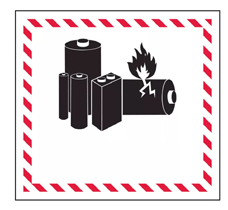
Remove the batteries from all system components during shipping and prolonged storage. Failure to do so may result in battery leakage, which may lead to risk of explosion, health risks, and/or damage.
Store and transport batteries using a suitable protective case that will keep batteries safely isolated from one another. Failure to do so may result in short circuits, which may lead to hazardous conditions including fire.
Lithium-ion batteries must be packaged and shipped by trained and certified personnel only. Never ship damaged batteries.
If you have any questions about the operation of your guidance system, please contact DCI Customer Service for assistance. Connect to DCI Customer Service with the Contact link in the DigiGuide App or find a list of offices in the back of any printed DigiGuide manual and on the DCI website: digital-control.com.
If you plan to store the battery packs for any period of time, please follow these guidelines:
Store and transport batteries using a suitable protective case that will keep batteries safely isolated from one another. Failure to do so may result in short circuits which may lead to hazardous conditions including fire.
Do not store the battery pack at temperatures greater than 113° F (45°C).
Do not store the battery pack in a fully discharged state.
Do not store the battery pack in the battery charger.
Do not store multiple batteries together where their terminals or other loose conductive materials may contact one another and cause a short circuit.
Never ship damaged batteries.
If a lithium-ion battery pack will be stored for an extended period of time, pre-charge the battery to a charge level of 30% to 50% (two or three LEDs illuminated on the meter).
Do not store the battery pack for more than one year unless it is periodically recharged to the 30% to 50% level.
Lithium batteries are regulated by UN3480 and UN3481 lithium-ion batteries.
Lithium batteries are considered Class 9 Miscellaneous Dangerous Goods under International Air Transportation Association (IATA) regulations; IATA regulation and Ground Transportation regulations 49 CFR 172 and 174 apply. These batteries must be packaged and shipped by trained and certified personnel only. Never ship damaged batteries.
When powered on, the FCD automatically displays the Remote Mode Locating Screen.
Clicking the button opens the Main menu.
- Remote mode
- Power off
- Settings
- Contrast adjustment
- System information
- Description of highlighted option
Click to move between icons, hold to select. If no selection is made within a few seconds, the FCD returns to the locating screen.
Stuff You Should Know

Registering your equipment activates the product warranty.
Registering also allows us to contact you if it is recovered after being lost or stolen.
If you want to enable the Lock Out Capability (LOC) feature, contact DCI support.
See the DCI website for warranty terms and conditions.
Contact your authorized DCI dealer or DCI to register your equipment.
You will need the equipment serial number and your company contact information.
Here’s where to find your serial number:
- Locator: in the battery compartment
- Transmitter: engraved on the steel body
- Remote display: decal on the back
Insert a battery.
Hold the button to power on.
Verify the locator type shown beside the telemetry icon (here, FF1) matches your locator.
If needed, use the Settings menu to change the locator type, otherwise continue to Jobsite Setup to verify locator data displays.
Ensure antenna and display connectors are free of debris and that the antenna pin is straight and intact.
Connect the telemetry antenna.
For long whip only – Mount antenna as high as possible and on a metal surface for maximum signal reception.
With the transmitter and locator paired and powered on, data automatically displays on the Remote Mode Locating Screen.
Roll the transmitter to ensure the roll clock moves correspondingly.
Data displays on the remote mode locating screen as soon as the locator receives data from a transmitter.
- Transmitter pitch
- Roll indicator
- Telemetry update meter
- Receiver type and telemetry channel
- FCD battery strength
- Transmitter battery strength (alkaline only)
- Transmitter temperature
When the locator takes a depth reading at the Locate Line (LL), the FCD displays the transmitter depth.
- Height-Above-Ground (HAG) setting on
- Depth of transmitter
If HAG is not on, the locator will be on the terrain line.
When the locator takes a depth reading at the Front Locate Point (FLP), the FCD displays the predicted depth *.
- Predicted depth of transmitter
If HAG is not on, the locator will be on the terrain line.
A depth reading taken at the Rear Locate Point (RLP) will still display a predicted depth, but because the locator can not distinguish between FLP and RLP, it will be inaccurate.
The Predicted Depth screen displays when the trigger is held with the locator at the Front Locate Point (FLP). The predicted depth is how deep the transmitter is calculated to be when it reaches the front locate point if it continues on its current path. The predicted depth will also display when the locator is at the Rear Locate Point (RLP), but it will not be correct.
Switching bands on the transmitter may provide better data, better depth, and/or better locate results as interference conditions change.
This procedure requires roll data from the transmitter. If you need to change bands on the transmitter but do not have roll data, see Changing Bands Using RRS Method under Advanced Topics.
Roll offset must be disabled before changing bands.
Position the transmitter at 10:00 (±1 clock position, or CP) and remain there for 10–18 seconds.
Rotate the transmitter clockwise to its 2:00 position (±1 CP) within 10 seconds and remain there for 10–18 seconds.
If any rotation is not completed within the prescribed time, or if any rotation continues for more than one full revolution, the transmitter band change is canceled.
Rotate the transmitter clockwise to its 7:00 position (±1 CP) within 10 seconds and wait.
When the procedure is finished, the transmitter changes bands, causing transmitter data to disappear.
Data will not disappear after a band change when using a Falcon Sub-k Rebar transmitter. Always rely on the locator operator to verify a band change.
The locator operator should now change to the other paired and calibrated band.
If the locator operator has not calibrated the second band, depth readings will not be correct.
Use a microfiber or soft cotton cloth with water and a mild liquid detergent to clean the screen and case.
Commercial cleaning products may damage the screen or case.
Do not pressure wash.
Carefully remove and store the antenna in the carry case to prevent damage.
If the remote display is installed in the drill console, place the protective plastic cover over the screen.
If the display can be removed from the rig, store it in the system carry case away from impact, moisture, and excessive temperatures.
Storage and transportation temperature must remain within -40° – 149°F (-40° – 65°C).
Click the button to open the Main menu.
Select Settings.
To change distance units, select Change Distance/Temperature Units.
Selecting metric units automatically changes temperature units to Celsius.
To change pitch units, select Change Pitch Units.
Click to change between units, hold to set.
Click the button to open the Main menu.
Select Settings.
Select Change Mode.
Click to select your locator, hold to set.
Switching bands on the transmitter using RRS (Repeating Roll Sequence) may provide better data, better depth, and/or better locate results as interference conditions change.
Use this procedure if you need to change bands on the transmitter but do not have roll data.
Rotate drill string for 10-15 seconds.
Remain at any clock position (CP) for at least 40 seconds.
Make a reference mark on the drill string.
You will use this mark as a visual roll indicator as you continue through these steps.
Complete one full clockwise rotation (±2 CP) of the reference mark within 0.5–30 sec., then wait 10–20 seconds.
If rotation is not completed within the prescribed time, or if any rotation continues for more than one full revolution, the transmitter band change is canceled.
Repeat step 3 two more times, for a total of three rotations (RRS3).
After the third rotation, leave the drill string at rest for a total of 60 seconds.
When the procedure is finished, the transmitter changes bands.
The locator operator should now change to the other paired and calibrated band.
If the locator operator has not calibrated the second band, depth readings will not be correct.
Once the locating specialist sets a target depth * on the locator, the FCD automatically enters Remote Steering mode.
Remote Steering information is only correct when the locator is properly positioned beyond the Front Locate Point and within the range limits of the transmitter and remote display.
Use the Target Steering app to view whether your current steering is on target.
Because Remote Steering does not provide up or down steering information, you must monitor the transmitter’s pitch.
As shown in the following example, the steering indicator will help you line up the drill head with the locator before it reaches the target.
Make small steering adjustments as needed to bring the steering indicator toward the target.
The closer the drill head is to the locator, the more sensitive the steering indicator will be.
When the horizontal distance is almost the same as the current depth, ensure the locating specialist moves the locator farther out to continue Remote Steering.
If the drill head passes this point, steering values on the display become invalid.
When the locator exits Remote Steering mode, the FCD automatically returns to the normal Remote Mode locating screen.
A value programmed into the locator, so it can be positioned ahead of the transmitter housing and used as a steering target. The value programmed should be the desired depth of the transmitter when it reaches the point below the locator. If a locator is placed above ground level, such as to provide separation from interference, that height must be added to the target depth.
Note: If using a Falcon Compact Display, only left/right steering information is available. The locator used with the Falcon Compact Display must still have a target depth set. This target depth can be any value.
Depth Increase in Inches (cm)
Slopes between 50% and 100% are provided for reference only and do not represent typical drilling conditions. All numbers are based on math only and do not take into account extremely soft or extremely hard soil conditions, which may cause depth values to vary.
Depth Increase in Inches (cm)
| % slope | Depth increase cm | % slope | Depth increase cm | % slope | Depth increase cm |
|---|---|---|---|---|---|
| 1 | 5 | 19 | 86 | 37 | 157 |
| 2 | 10 | 20 | 89 | 38 | 163 |
| 3 | 13 | 21 | 94 | 39 | 165 |
| 4 | 18 | 22 | 99 | 40 | 170 |
| 5 | 23 | 23 | 102 | 41 | 173 |
| 6 | 28 | 24 | 107 | 42 | 178 |
| 7 | 33 | 25 | 112 | 43 | 180 |
| 8 | 36 | 26 | 114 | 44 | 183 |
| 9 | 41 | 27 | 19 | 45 | 188 |
| 10 | 46 | 28 | 124 | 46 | 191 |
| 11 | 51 | 29 | 127 | 47 | 196 |
| 12 | 53 | 30 | 132 | 50 | 203 |
| 13 | 58 | 31 | 135 | 55 | 221 |
| 14 | 64 | 32 | 140 | 60 | 236 |
| 15 | 69 | 33 | 142 | 70 | 262 |
| 16 | 71 | 34 | 147 | 80 | 284 |
| 17 | 76 | 35 | 150 | 90 | 305 |
| 18 | 81 | 36 | 155 | 100 | 323 |
Slopes between 50% and 100% are provided for reference only and do not represent typical drilling conditions. All numbers are based on math only and do not take into account extremely soft or extremely hard soil conditions, which may cause depth values to vary.
| Country | Allowed Frequencies (MHz) | Limitations | Region (legacy) | Region (new) |
|---|---|---|---|---|
| Austria | 458.6, 458.65, 458.7, and 458.75 | Yes* | UK | GB |
| Belgium | 458.6, 458.65, 458.7, and 458.75 | Yes* | UK | GB |
| Bulgaria | 458.6, 458.65, 458.7, and 458.75 | Yes* | UK | GB |
| Croatia | 458.6, 458.65, 458.7, and 458.75 | UK | GB | |
| Cyprus | 458.6, 458.65, 458.7, and 458.75 | UK | GB | |
| Czech Republic | 449.8, 449.85, 449.9, 449.95 | UK | GB | |
| Denmark | 458.6, 458.65, 458.7, and 458.75 | UK | GB | |
| Estonia | 449.8, 449.85, 449.9, and 449.95 | Yes* | ES | ES |
| Finland | 458.6, 458.65,458.7, and 458.75 | UK | GB | |
| France | 458.6, 458.65, 458.7, and 458.75 | UK | GB | |
| Germany | 458.6, 458.65, 458.7, and 458.75 | UK | GB | |
| Greece | 458.6, 458.65, 458.7, and 458.75 | UK | GB | |
| Hungary | 433.65 and 433.70 | Yes* | SW or SU | CH |
| Iceland | 458.6, 458.65, 458.7, and 458.75 | UK | GB |
| Country | Allowed Frequency (MHz) | Limitations | Region (legacy) | Region (new) |
|---|---|---|---|---|
| Ireland | 458.6, 458.65, 458.7, and 458.75 | UK | GB | |
| Italy | 458.6, 458.65, 458.7, and 458.75 | Yes* | UK | GB |
| Latvia | 449.8, 449.85, 449.9, 449.95 | Yes* | UK | GB |
| Liechtenstein | 433.65 and 433.70 | SW or SU | CH | |
| Lithuania | 449.8, 449.85, 449.9, 449.95 | Yes* | UK | GB |
| Luxembourg | 458.6, 458.65, 458.7, and 458.75 | Yes* | UK | GB |
| Malta | 458.6, 458.65, 458.7, and 458.75 | Yes* | UK | GB |
| Netherlands | 451.03 and 451.09 | Yes* | NL | NL |
| Norway | 458.6, 458.65, 458.7, and 458.75 | UK | GB | |
| Poland | 458.6, 458.65, 458.7, and 458.75 | UK | GB | |
| Portugal | 458.1125, 458.125, 458.1375, 458.15 | PT | ||
| Romania | 433.65 and 433.70 | UK | CH | |
| Slovak Republic | 458.6, 458.65, 458.7, and 458.75 | UK | GB | |
| Slovenia | 449.8, 449.85, 449.9, 449.95 | Yes* | UK | GB |
| Spain | 449.8, 449.85, 449.9, and 449.95 | ES | ES | |
| Sweden | 458.6, 458.65, 458.7, and 458.75 | UK | GB | |
| Switzerland | 433.65 and 433.70 | SW or SU | CH |
*Individual user license required–check with your local authority. Unless otherwise noted, the maximum radiated power output is limited to 100m WERP. Please contact DCI at productcompliance@digital-control.com, if additional technical information or translation is required.
The FAR5 contains a BLE Radio with the following specifications: Frequency Bands: 2402-2480 mHz Transmit Power: 0.00135 W EIRP
The AEO2 contains WiFi/BT and Cellular/GPS radios which operate on the following bands:
CE BANDS
GSM900: 880.2 – 914.8 MHz GSM1800: 1710.2 – 1784.8MHz
LTE Band 1: 1920 – 1980 MHz
LTE Band 3: 1710 – 1785 MHz
LTE Band 5: 824 – 849 MHz
LTE Band 7: 2500 – 2570 MHz
LTE Band 8: 880 – 915 MHz
LTE Band 20: 832 – 862 MHz
LTE Band 28: 703 – 748 MHz
LTE Band 38: 2570 – 2620 MHz
LTE Band 40: 2300 – 2400 MHz
LTE Band 41: 2496 – 2690 MHz
Contact
DCI USA
19625 62nd Ave S, Suite B103
Kent, WA USA 98032
DCI@digital-control.com
1.800.288.3610
1.425.251.0559
DCI Australia
2/9 Frinton Street Southport
Queensland 4215 Australia
DCI.Australia@digital-control.com
+61.7.5531.4283
+61.7.5531.2617
DCI China
368 Xingle Road Huacao Town
Minhang District Shanghai 201107, P.R.C
DCI.China@digital-control.com
+86.400.100.8708
+86.21.6432.5186
DCI Europe
Brueckenstraße 2
97828 Marktheidenfeld Germany
DCI.Europe@digital-control.com
+49.9391.810.6100
+49.9391.810.6109
DCI India
Unit No. 1022, 10th Floor DLF Tower B Jasola District Center
New Delhi 110025 India
DCI.India@digital-control.com
+91.11.4507.0444
+91.11.4507.0440
DCI Philippines
404-405 Energy Opt. Bldg Prime St, Madrigal Business Park 2
Alabang Muntinlupa City, Philippines 1780
DCI.Philippines@digital-control.com
(02)79802647
+632-79802647